
 Hardware
SIM7080G Module
NB-IoT/LTE-M cellular + GNSS plug-in module for the A0 base board (BUS1/BUS2).
SIM7080G
Cellular uplink module based on the SIMCom SIM7080G — NB-IoT / LTE-M (Cat-M) plus GNSS (GPS/GLONASS/BeiDou/Galileo). Plugs into A0 BUS1 or BUS2, controlled over UART with AT commands.
Key Features
- NB-IoT and LTE-M (Cat-M) cellular uplink
- GNSS positioning for asset tracking
- On-board nano-SIM socket (U3) — no external SIM holder needed
- Dedicated RF + GNSS antenna connectors (J4 = LTE, J3 = GNSS)
- Powered from the expansion slot (+3V3)
Antennas
- J4 is the LTE connector (modem
RF_ANT), J3 is the GNSS connector (modemGNSS_ANT). Do not swap them. - J3 needs an active GNSS antenna: the centre pin of the J3 coaxial connector carries a +3V3 bias for the antenna LNA. Use an active (powered) GNSS antenna rated for 3.3 V bias; a passive antenna will see DC on its feed and will underperform.
SIM Socket
The module carries its own nano-SIM socket U3 (NANO SIM XG6P, wired to the modem SIM_VDD/SIM_RST/SIM_CLK/SIM_DATA with ESD protection). Insert a provisioned NB-IoT/LTE-M SIM before bring-up — the module page previously omitted this, but there is no SIM holder on the base board itself.
Image
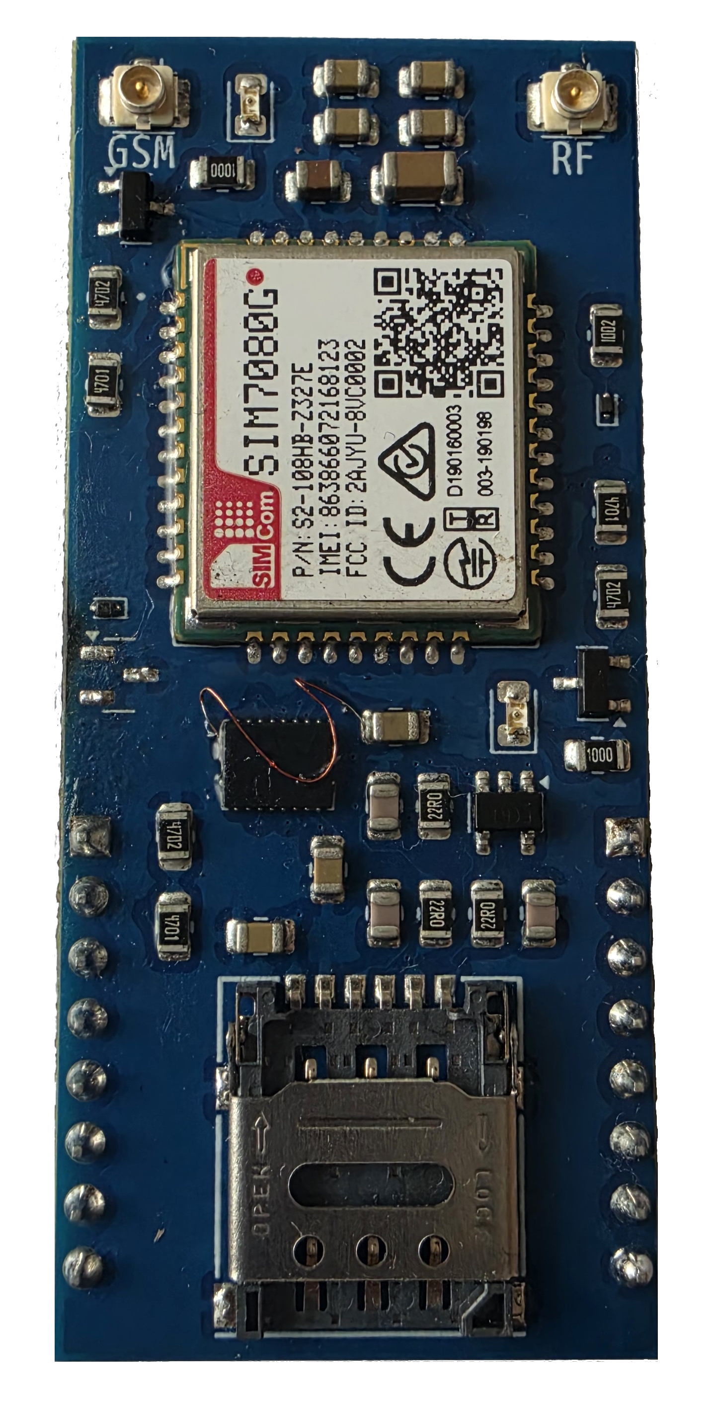
Front PCB
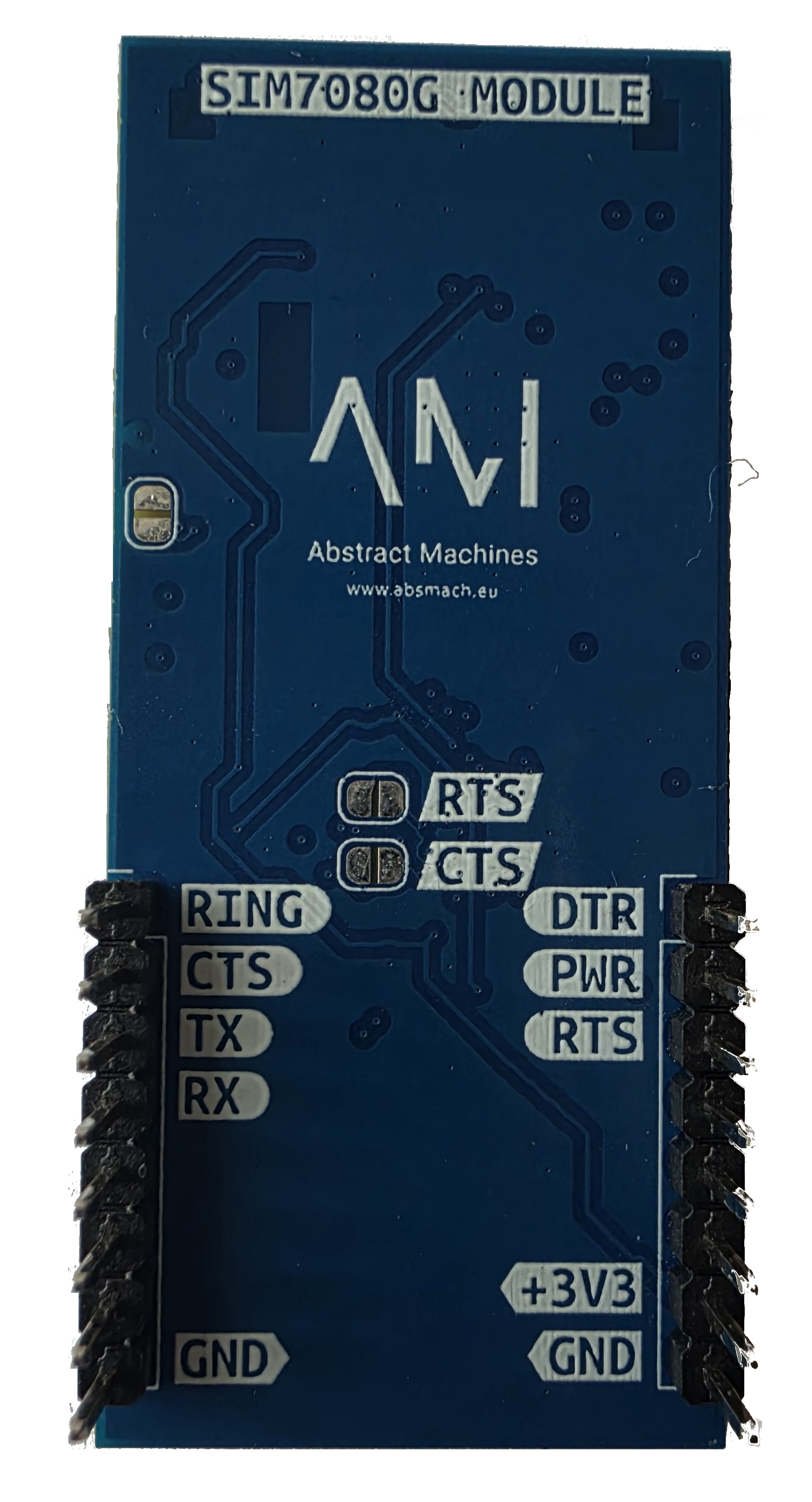
Back PCB
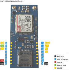
Front Pinout
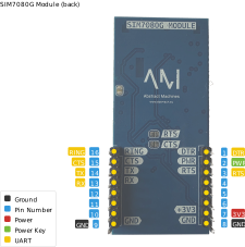
Back Pinout
BUS1 Wiring (verified)
| Signal | ESP32-C6 | BUS1 Pin |
|---|---|---|
| Modem TX → ESP RX | GPIO16 | J3 pin 3 |
| Modem RX ← ESP TX | GPIO17 | J3 pin 4 |
| PWRKEY | GPIO1 | J1 pin 2 |
| RING | GPIO3 | J3 pin 1 |
| CTS | GPIO0 | J3 pin 2 (via JP3 — ships open) |
| RTS/DTR | GPIO2/GPIO14 | J1 pin 3 / J1 pin 1 (via U1 switch; RTS via JP2 — ships open) |
| VCC/GND | +3V3/GND | J1 pin 7 / J3 pin 8 |
UART @115200 baud. Bring-up: SIM7080G Bring-up; firmware in firmware/: a0_sim7080g, a0_sim7080g_pwrkey, a0_sim7080g_bringup, a0_sim7080g_term.
DCD on hold: the modem
UART1_DCDoutput is currently unconnected on the module. Do not wire it — routing is on hold until absmach/a0#29 resolves the collision withSCLon BUS2 J2 pin 5.
Flow Control Jumpers
Hardware flow control is optional and ships disconnected:
- JP3 gates CTS, JP2 gates RTS (both
SolderJumper-2_Openon the module). - With the jumpers open (factory state), run without RTS/CTS or with software flow control.
- To use hardware flow control, close JP2 and JP3 with a solder blob. The level shifter (U1 TXB0108) then passes RTS/CTS between the modem and the base-board bus.
Status LEDs
Two LEDs give useful signal during bring-up (driven from the modem via NPN transistors):
- D3 — STATUS (modem pin 42): lights while the modem is powered and running. Dark means the modem is off or held in reset — check PWRKEY and the +3V3 supply first.
- D4 — NETLIGHT (modem pin 41): blinks with network activity — fast blink while searching, slow blink once registered. Solid/off with no blink after power-up usually means no antenna or no SIM.
Firmware-Update Path (JP1 + Test Points)
- JP1 (solder jumper, ships open) is the modem USB firmware-update path: it routes the modem USB-boot signal (U2 pin 20, via D1/R1). Close JP1 to put the modem into USB download mode for firmware updates, leave it open for normal operation.
- TP2, TP3 and TP4 are the accompanying modem-USB test points on the module. Use them to probe or wire the modem USB signals during a firmware update; refer to the module silkscreen and
modules/sim7080g/sim7080g.kicad_schfor the exact signal on each point.
Power Budget
The module is fed from a single +3V3 pin (J1 pin 7 on BUS1 / J4 pin 7 on BUS2, modem VBAT pins 34/35 via the on-board bulk caps including 100 µF C9).
- Cellular transmit bursts (NB-IoT/LTE-M) draw sharp current peaks — budget up to ~500 mA peak on the +3V3 rail during transmission.
- Keep the module supply short and low-impedance, leave the bulk capacitance in place, and do not share the slot +3V3 pin with other hungry loads during transmit.
- The base-board +3V3 rail comes from the AMS1117-3.3 LDO pair (see the A0 Base Board) — when both slots are populated, sum the transmit peaks before assuming headroom.
Schematics & Sources
- Schematic (PDF) — GitHub
- KiCad source — sim7080g.kicad_sch
- Module README — GitHub
References
- SIMCom SIM7080G — product page · AT command manual (PDF) · hardware design manual